Video Wall Setup
+3
icke_siegen
Gringoloco
Sebastien
7 posters
 Video Wall Setup
Hello.
Is there any way to do the video maping of a LED wall inside the Avolites Media?
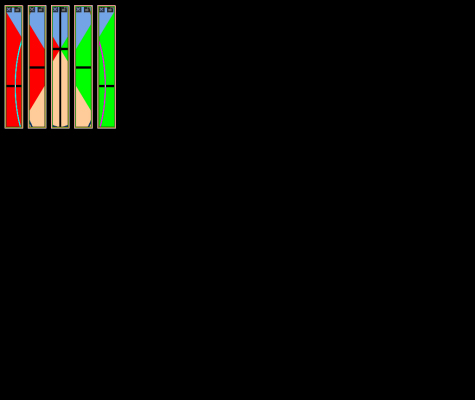
For exemple here is my LED Wall.

I would like to have an output like that for exemple. So on my video output I have only the part of the video I need and I can bring the LED tiles closer in my LED wall contoler.
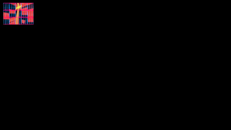
I found a way to do that a bit with the maping editor. But it look like to be only for Video Projector setting. And you can't choose the pixel size of each tiles to have a pixel to pixel output...
If you have any idea.
++, Seb.
Is there any way to do the video maping of a LED wall inside the Avolites Media?
For exemple here is my LED Wall.

I would like to have an output like that for exemple. So on my video output I have only the part of the video I need and I can bring the LED tiles closer in my LED wall contoler.

I found a way to do that a bit with the maping editor. But it look like to be only for Video Projector setting. And you can't choose the pixel size of each tiles to have a pixel to pixel output...
If you have any idea.
++, Seb.
Sebastien- Posts : 137
Join date : 2013-02-28
Age : 41
Location : France
 LED Mapping
Video Output module
Right click
Load Alternate Skin
LED Config
Options for window position (X/ Y coordinates)
Window size (LED DX: LED DY)
Screen (Port) Output
Click the LED Config button to turn on or off.
I am currently using for 4 separate LED walls.
Another tip:
Insert module
Display
Template Generator
Tie the output of this to each LED window.
It provides a generated test grid for each of the outputs and shows the pixel size on each LED wall. You only need one of these. The output can tie to multiple LED windows. I have found very useful to fix position errors when off by one or two pixels.
Gringoloco- Posts : 73
Join date : 2012-11-30
 Re: Video Wall Setup
I cant do what I wanna do with your system I think.
With your system I cant crop part of the screen and put it where I want on the output.
I wanna crop some part of my screen and I wanna put it where I want on my output. For that I need X, Y video position / X, Y crop size / X,Y position output / X, Y Size of the crop on the output.
With your system I cant crop part of the screen and put it where I want on the output.
I wanna crop some part of my screen and I wanna put it where I want on my output. For that I need X, Y video position / X, Y crop size / X,Y position output / X, Y Size of the crop on the output.
Sebastien- Posts : 137
Join date : 2013-02-28
Age : 41
Location : France
 Re: Video Wall Setup
This method gives you a window with x y position on your output of x y size.
The x y clip position and x y crop is on the mixer layer.
Stage patch
Double click the mixer on your device
Open up the layer
Size, aspect ratio should get you to your desired result.
This is not the only way to achieve your end result. Just the approach I would take after using another media server for several long years...
Gringoloco- Posts : 73
Join date : 2012-11-30
 Re: Video Wall Setup
No. Im not looking for that. And it's not possible like that I think.
I don't wanna change anything on the mix. The mix are patched like a Catalyst on a Grand MA.
I have 1 3D model. And I wanna split it in different part on the same output.
Inside the Catalyst you create 5 different mix and you put it where you want on the output. You put offset on the mix and that's finish...
If I try your solution it means I need to use 5 different layer to have all the image. And If tomorrow I use 30 screen?
There is no way to crop a part of the video and put it with the size you want and position you want on the output???
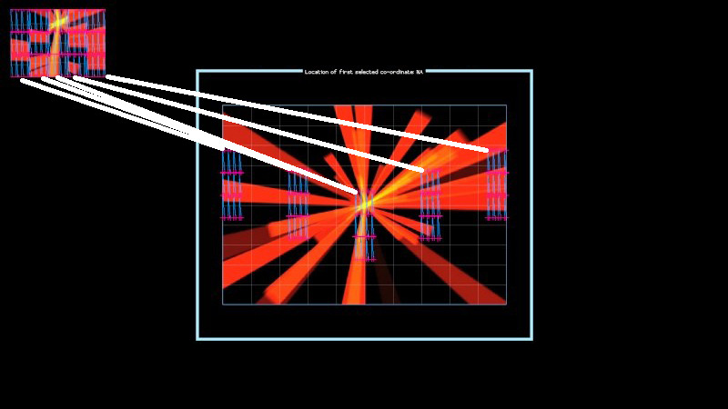
What is the different to between this 2 setup if at the end the output is the same? It means nothing...
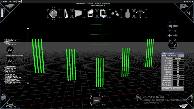

I don't wanna change anything on the mix. The mix are patched like a Catalyst on a Grand MA.
I have 1 3D model. And I wanna split it in different part on the same output.
Inside the Catalyst you create 5 different mix and you put it where you want on the output. You put offset on the mix and that's finish...
If I try your solution it means I need to use 5 different layer to have all the image. And If tomorrow I use 30 screen?
There is no way to crop a part of the video and put it with the size you want and position you want on the output???

What is the different to between this 2 setup if at the end the output is the same? It means nothing...


Sebastien- Posts : 137
Join date : 2013-02-28
Age : 41
Location : France
 Re: Video Wall Setup
I'd say this is definitely something for Gringoloco's first solution: LED config in the Video Output module. You simply create several of those modules, wire them all the same and have it go to the same output, and adjust the in and out pixel settings.
Probably you will use 5 video output modules in your setup - one per column of your tiles.
If you could give some more data, e.g. exact pixel counts of your tiles and positions, it would be easy to make a dedicated example for you.
Probably you will use 5 video output modules in your setup - one per column of your tiles.
If you could give some more data, e.g. exact pixel counts of your tiles and positions, it would be easy to make a dedicated example for you.
icke_siegen- Posts : 33
Join date : 2013-02-24
 Re: Video Wall Setup
Or maybe better, I just find out in "Insert System patch" a module named "LED output with position...". seems to be what you looking for
(version 7.0.0.702)
(version 7.0.0.702)

f.antoci- Posts : 19
Join date : 2012-11-20
Age : 36
Location : Italy
 Re: Video Wall Setup
Hey Sebastien,
The problem here with your outputs being the same is that the led config only takes a render input (yellow port) and so does not know any information from your 3D model on how to draw the outputs. Your set up passes the canvas from the fixture, which also has no indication on the UV drawing co-ordinates specified by the model. Your canvas output is essentially the edited media after all of your layer transformations/effects etc. The screen fixture output is where all the UV information comes from. To see what I'm on about, in the top bar go to 'view -> inspector'. And with this open hover over the 'canvas out' from your screen. You will notice there is no UV transforms.
So the way to apply this to the output is not to use the LED Config alternate skin, but the 'Multi_Unit_LED_Config' skin. Just right click on a video out module and choose 'Load alternate Skin' and you should be able to find it.
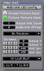
So this is a much more advanced LED output module, which takes a texture input, and more importantly a screen fixture input (which contains all our lovely UV mapping data). Now that you have found the right module to use, we have two different approaches that you can use. If you want gaps in your output between each screen, then we will need 5 different modules for each screen. If you are happy to have no gaps. Then the module can output the whole data for you.
Just as a quick overview of what this module is achieving, I will list the parameters:
- Your screen fixture input and fixture texture input are self explanatory. The texture is what you want to draw, and the screen fixture contains all your mapping information.
- The output unit count tells the module how many 'units' to draw. The units in this case are the 'objects / elements' in your 3d model. So depending on how the model was created depends on how this is drawn. I would presume that each of your 5 screens is an individual 'Unit'. So if this was set to 5, then it would draw everything, if it is set to 1 then it would draw one of the screens.
- The Model Unit Offset tells what 'Unit/object/element' to draw. So we start here with a zero based number, where 0 represents the 1st Unit. So if you was drawing one unit 0 would be the first screen, 1 the second and so on. Bear in mind the numbers are based on the order that the units was created in your 3d modelling software, not necessarily on the order that they look on the screen.
- Rotation and flip just transforms your texture that is being draw on that unit.
- Screens are just what you are outputting to. In your example I have 5 screens all outputting to screen 1. You would want to output to the same screens here.
- Output X & Output Y are the x y pixel values of where you start drawing the units on your OUTPUT.
- Unit xPx & unit yPx are the sizes of your units on the output.
- The next drop down box tells how to draw your outputs from the UV Co-ordinates. So there are different UV Methods, left to right, bottom to top etc.
- And finally the last drop down box tells how to draw the outputs from the Vertex Co-ordinates.
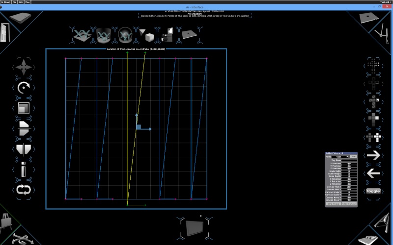
So back to your example. I made a quick model using 5 screens and the model merge function on the stage patch. I then UV Mapped it to get a planar unwrapping along the XY Axis. This gave me this model:
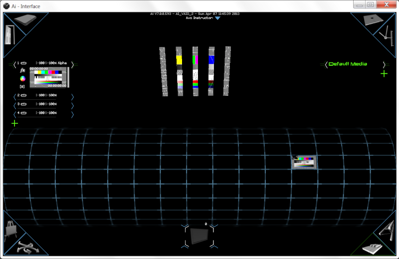
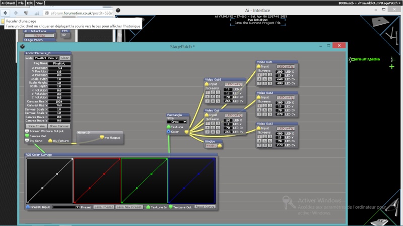
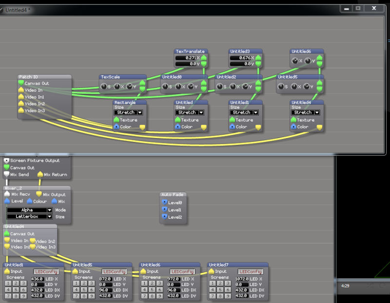
It's slightly different to your model, but the concepts that come next are the same. So after this I needed to add the output modules, I also added your colour curves transformation so you can see how they all link in. Here is the stage patch:
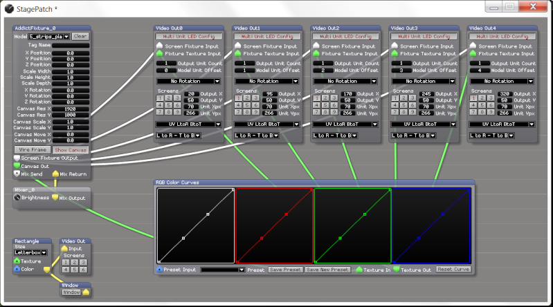
So I've started by moving the image 20 pixels in by 50 pixels down. I then have duplicated the multi unit led config module so that we can configure 5 outputs (one for each screen) and because my outputs are 70px wide, I have added 75pixels to the start of the next modules consecutively. Giving us a 5 pixel space in between the outputs.
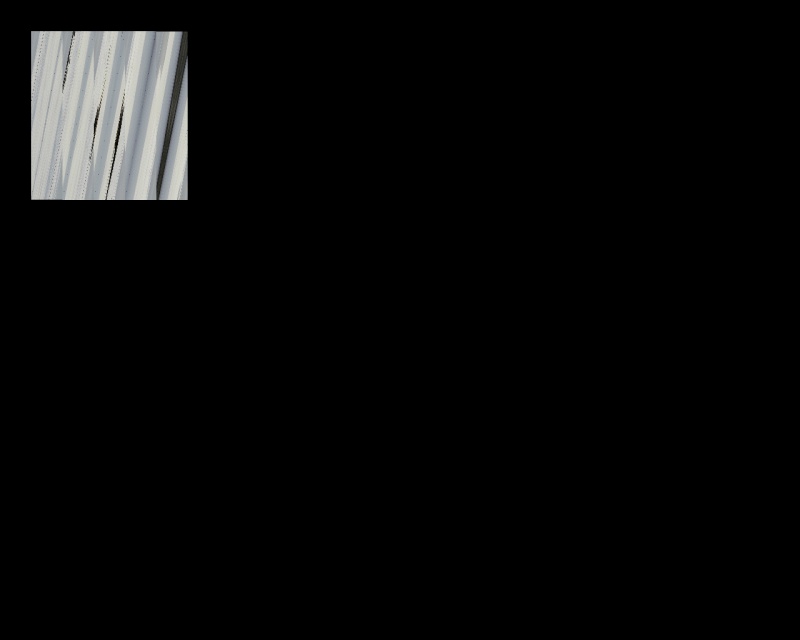
Here is the output:
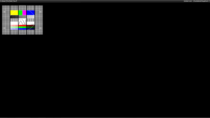
So as you can see from the output, we are drawing the whole image with the gaps specified. I hope this helps. I've included the project that I used to make this demo and the model that I quickly made. You just need to drag the model on the screen fixture to see it loaded in. Then press the outputs to get the result.
Ciaran
P.S This forum wouldn't med upload the project, so you can find it here: https://docs.google.com/file/d/0ByPUwEa1WespN0M5U2dtN2RINk0/edit?usp=sharing
The problem here with your outputs being the same is that the led config only takes a render input (yellow port) and so does not know any information from your 3D model on how to draw the outputs. Your set up passes the canvas from the fixture, which also has no indication on the UV drawing co-ordinates specified by the model. Your canvas output is essentially the edited media after all of your layer transformations/effects etc. The screen fixture output is where all the UV information comes from. To see what I'm on about, in the top bar go to 'view -> inspector'. And with this open hover over the 'canvas out' from your screen. You will notice there is no UV transforms.
So the way to apply this to the output is not to use the LED Config alternate skin, but the 'Multi_Unit_LED_Config' skin. Just right click on a video out module and choose 'Load alternate Skin' and you should be able to find it.

So this is a much more advanced LED output module, which takes a texture input, and more importantly a screen fixture input (which contains all our lovely UV mapping data). Now that you have found the right module to use, we have two different approaches that you can use. If you want gaps in your output between each screen, then we will need 5 different modules for each screen. If you are happy to have no gaps. Then the module can output the whole data for you.
Just as a quick overview of what this module is achieving, I will list the parameters:
- Your screen fixture input and fixture texture input are self explanatory. The texture is what you want to draw, and the screen fixture contains all your mapping information.
- The output unit count tells the module how many 'units' to draw. The units in this case are the 'objects / elements' in your 3d model. So depending on how the model was created depends on how this is drawn. I would presume that each of your 5 screens is an individual 'Unit'. So if this was set to 5, then it would draw everything, if it is set to 1 then it would draw one of the screens.
- The Model Unit Offset tells what 'Unit/object/element' to draw. So we start here with a zero based number, where 0 represents the 1st Unit. So if you was drawing one unit 0 would be the first screen, 1 the second and so on. Bear in mind the numbers are based on the order that the units was created in your 3d modelling software, not necessarily on the order that they look on the screen.
- Rotation and flip just transforms your texture that is being draw on that unit.
- Screens are just what you are outputting to. In your example I have 5 screens all outputting to screen 1. You would want to output to the same screens here.
- Output X & Output Y are the x y pixel values of where you start drawing the units on your OUTPUT.
- Unit xPx & unit yPx are the sizes of your units on the output.
- The next drop down box tells how to draw your outputs from the UV Co-ordinates. So there are different UV Methods, left to right, bottom to top etc.
- And finally the last drop down box tells how to draw the outputs from the Vertex Co-ordinates.
So back to your example. I made a quick model using 5 screens and the model merge function on the stage patch. I then UV Mapped it to get a planar unwrapping along the XY Axis. This gave me this model:

It's slightly different to your model, but the concepts that come next are the same. So after this I needed to add the output modules, I also added your colour curves transformation so you can see how they all link in. Here is the stage patch:

So I've started by moving the image 20 pixels in by 50 pixels down. I then have duplicated the multi unit led config module so that we can configure 5 outputs (one for each screen) and because my outputs are 70px wide, I have added 75pixels to the start of the next modules consecutively. Giving us a 5 pixel space in between the outputs.
Here is the output:

So as you can see from the output, we are drawing the whole image with the gaps specified. I hope this helps. I've included the project that I used to make this demo and the model that I quickly made. You just need to drag the model on the screen fixture to see it loaded in. Then press the outputs to get the result.
Ciaran
P.S This forum wouldn't med upload the project, so you can find it here: https://docs.google.com/file/d/0ByPUwEa1WespN0M5U2dtN2RINk0/edit?usp=sharing

Ciaran- Posts : 32
Join date : 2012-11-14
Age : 35
Location : Avolites Media
 Re: Video Wall Setup
Wow Perfect !!! Thank you.
++, Seb.
++, Seb.
Sebastien- Posts : 137
Join date : 2013-02-28
Age : 41
Location : France
 Re: Video Wall Setup
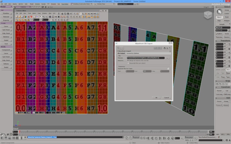
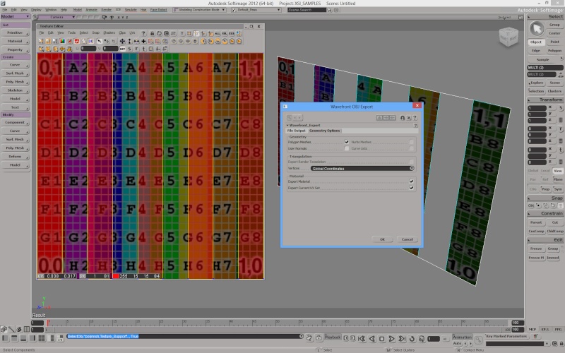
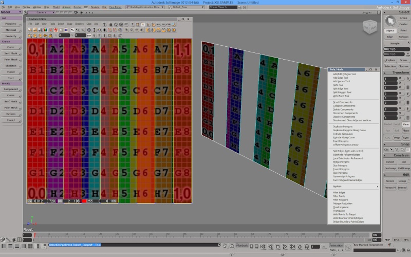
I have just a little problem. My 3D objects are exported from Softimage XSI to *.obj
The problem is the *.ojb files are tringulate and not quadrangulate.

But when I open it in Softimage the polygone looks quad...
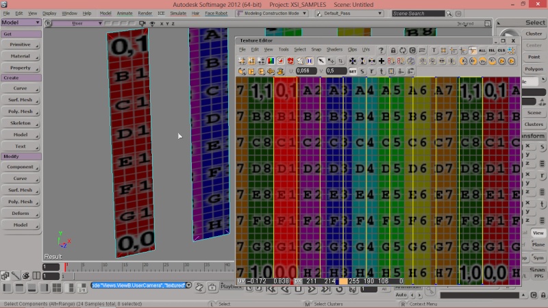
Can I change that in Avolites Media or there is a way to use 2 triangulate polygone for a square one?
The problem is the *.ojb files are tringulate and not quadrangulate.

But when I open it in Softimage the polygone looks quad...

Can I change that in Avolites Media or there is a way to use 2 triangulate polygone for a square one?
Sebastien- Posts : 137
Join date : 2013-02-28
Age : 41
Location : France
 Re: Video Wall Setup
the 4th option down on the right in the canvas editor page lets you work with faces and not triangulated polygons 
 Re: Video Wall Setup
Hey Seb,
It's quite interesting looking at your .obj file and how it reacts in the canvas editor. Unfortunately it looks like the software you are using to build the model is exporting it in the triangles format. We actually do everything in triangles under the hood (most applications do actually, because the graphics card has to turn it back into triangles later on) but try to cover up some of the lines in different modes. If when you was on element mode and you still saw the triangles then it seems that's the way it was exported unfortunately. It would be nice if you could share the model with us, so we could take a look at it. Maybe there are some settings that you can configure when exporting?
And to see your updates on your output you need to save the model after your transforms. To do this click on the icon in the top menu that looks like a floppy disk. This will save your UV editing and create a new model in our own .SV3D file type. The software will then reload this back into Ai Ready to go.
So it's good to note that on the preview you can see a live update. But if you want to see this on your output than you need to save the model to get the effect

Ciaran- Posts : 32
Join date : 2012-11-14
Age : 35
Location : Avolites Media
Sebastien- Posts : 137
Join date : 2013-02-28
Age : 41
Location : France
 Re: Video Wall Setup
And here is the link for my *.obj file : https://drive.google.com/folderview?id=0B4KgStaGPbeGMUZ5MlB3R2xVMWc&usp=sharing
When I open this file in softimage it look Quad.
When I open this file in softimage it look Quad.
Sebastien- Posts : 137
Join date : 2013-02-28
Age : 41
Location : France
 Re: Video Wall Setup
guys...
right click in the output module > go for advance LED mapping module.
there are some options there to play around with the way you constructed your model / 3d surface. you can alter the draw order ...
standard it goes 1>2>3>4. but you can change this to 1>2>4>3. also have a look at the rotating / flip / mirror option.
did a lot with the advance LED last year and it will solve the issues your having.
R
www.tenfeet.eu
 Re: Video Wall Setup
Rik wrote:guys...
right click in the output module > go for advance LED mapping module.
there are some options there to play around with the way you constructed your model / 3d surface. you can alter the draw order ...
standard it goes 1>2>3>4. but you can change this to 1>2>4>3. also have a look at the rotating / flip / mirror option.
did a lot with the advance LED last year and it will solve the issues your having.
R
www.tenfeet.eu
Same problem it's didnt solve anything. Avolite Media is working with Quad, not Triangulate...
Sebastien- Posts : 137
Join date : 2013-02-28
Age : 41
Location : France
 Re: Video Wall Setup
int the canvas editor there's a row of tools on the right... one of them is for the triangles. other for the polygons.
Sebastien wrote:Rik wrote:guys...
right click in the output module > go for advance LED mapping module.
there are some options there to play around with the way you constructed your model / 3d surface. you can alter the draw order ...
standard it goes 1>2>3>4. but you can change this to 1>2>4>3. also have a look at the rotating / flip / mirror option.
did a lot with the advance LED last year and it will solve the issues your having.
R
www.tenfeet.eu
Same problem it's didnt solve anything. Avolite Media is working with Quad, not Triangulate...
 Re: Video Wall Setup
Rik wrote:int the canvas editor there's a row of tools on the right... one of them is for the triangles. other for the polygons.Sebastien wrote:Rik wrote:guys...
right click in the output module > go for advance LED mapping module.
there are some options there to play around with the way you constructed your model / 3d surface. you can alter the draw order ...
standard it goes 1>2>3>4. but you can change this to 1>2>4>3. also have a look at the rotating / flip / mirror option.
did a lot with the advance LED last year and it will solve the issues your having.
R
www.tenfeet.eu
Same problem it's didnt solve anything. Avolite Media is working with Quad, not Triangulate...
This is just tool to move Poly or Triangle. But it's just made to change the UV position. It change nothing about Quad or Triangle.
But it's working with rotation change, vertex order change. Thank you for your help.
Sebastien- Posts : 137
Join date : 2013-02-28
Age : 41
Location : France
 Re: Video Wall Setup
yep.
it's really important to know how a 3d-mesh is constructed.
in every 3d-mesh, even as it has multiple polygons there's always an 'indice' / index count of the vertices / edges /polygons.
It gives a number to the polygons. This is used by the 3d packages in general to structure a 3d-mesh (quad or triangulated).
The advance LED mapper can read this 'indice' / index number from your 3d-file.
R
 Similar topics
» Mapping AI onto a video wall with Gaps
» how to approach this setup
» Ai Video Tutorials
» Video Out Module Question
» Video formats in AI?
» how to approach this setup
» Ai Video Tutorials
» Video Out Module Question
» Video formats in AI?
Permissions in this forum:
You cannot reply to topics in this forum